|
December, 1953 |
John Deere Service Bulletins |
No. 210 |
|
INSTALLATION INSTRUCTIONS AM2095T BOTTOM GUARD AND FRONT DRAWBAR ATTACHMENT FOR JOHN DEERE MODEL "40" CRAWLER TRACTOR |
||
|
December, 1953 |
John Deere Service Bulletins |
No. 210 |
|
INSTALLATION INSTRUCTIONS AM2095T BOTTOM GUARD AND FRONT DRAWBAR ATTACHMENT FOR JOHN DEERE MODEL "40" CRAWLER TRACTOR |
||
If the tractor is equipped with an M1023T bumper, remove it. Also remove the light duty sod pan.
Bumper.
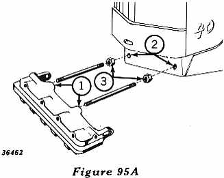
In order to install the bottom plate assembly on the tractor, the AM2094T bumper attachment must first be in place. This bumper is packaged with two bumper tension rods and two 7/8-inch hex nuts.
 Refer to Figure
95A.
Refer to Figure
95A.
1. Thread one end of each tension rod in the tapped holes in the rear of the bumper.
2. Insert tension rods through holes in the radiator support casting.
3. Install hex nuts on other end of tension rods and tighten
securely.
Bottom Guard.
Raise front end of tractor.
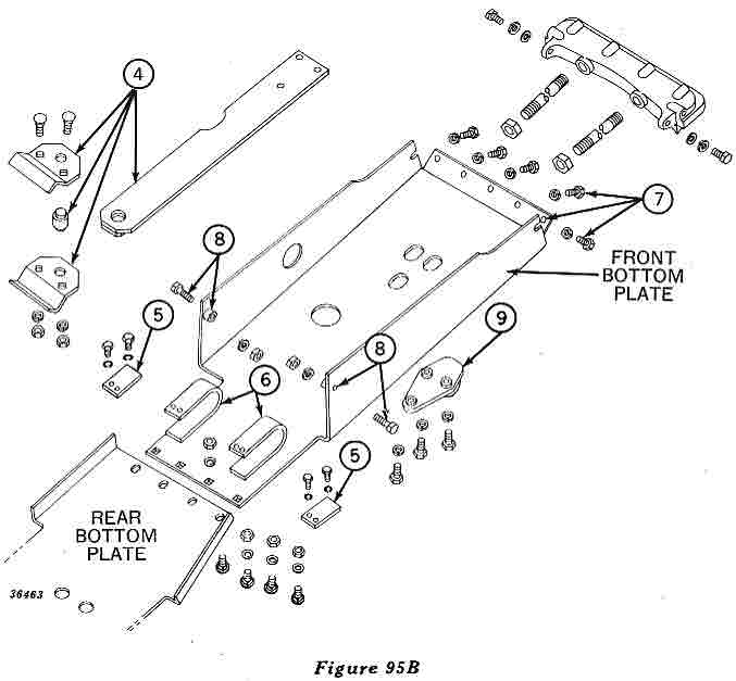 Refer to Figure 95B.
4. Using two 5/18 x 2-1/2-inch carriage bolts, attach front clevis plates to center of front cross member of tractor, inserting pivot pin through large hole in front drawbar and into round holes in clevis plates.
5. If the tractor is a Model "MC," or a Model "40" Crawler with Serial No. lower than 4OC-62264, install spacers on inside of the two hangers at the rear of the front bottom plate.
NOTE: These spacers are not included with the bottom guard attachment. To order spacers, specify AM2245T Bottom Plate Spacer Attachment.
6. Hook these hangers on the front cross member of the tractor. The tractor must be raised high enough so that hangers will slip over the flat section of the cross member.
7. Raise front of front bottom plate into position against bumper, and attach bottom plate to front of bumper with five 7/16 x 1-1/8 inch cap screws and 7/16-inch lock washers. Attach front bottom plate to sides of bumper with two 7/16 x 1-1/4-inch cap screws, 7/16 inch lock washers and 15/32 x 1-inch plain washers.
8. Attach front bottom plate to side frame assembly with two 7/16 x 2-1/4-inch cap screws, 7/16-inch lock washers, and 7/16 inch hex nuts.
9. Position front hitch under three large elongated holes in front
bottom plate and attach to front drawbar with three 5/8 x 1-3/4-inch
cap screws and 5/8-inch lock washers. Lower front of tractor to floor.
The rear drawbar quadrant is held to the final drive housings by hollow
dowels and bolts. Remove the lower bolt on each side of the
quadrant. Insert 5/8-inch cap screws into the threaded hollow dowels
and drive dowels out with a punch, from the outside of the housing.
Discard bolts and dowels.
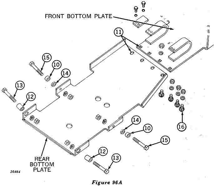 Refer to Figure 96A.
10. Install short threaded hollow dowels in lower front counterbore of each final drive housing.
11. Slide rear bottom plate under tractor with four elongated holes toward front of tractor. Place front of rear bottom plate on top of rear edge of front bottom plate and align elongated holes with square holes in front bottom plate.
12. Raise rear bottom plate into position, with holes in plate in line with holes in final drive housings. Drive long threaded hollow dowels through holes in bottom plate and lower holes in drawbar quadrant, into final drive rear counterbore.
13. Install a 1/2 x 4-1/2-inch cap screw in rear hole of each final drive housing and through dowel. Secure with 17/32 x 1-1/2-inch flat washer and 1/2-inch hex nut.
14. Slip a spacer between dowel in final drive front hole and corresponding hole in bottom plate.
15. Install a 1/2 x 4-1/2-inch cap screw in front hole of each final drive housing and through dowel, spacer and hole in bottom plate. Secure with 17/32-inch flat washer and 1/2-inch hex nut
16. From bottom side, insert the four 5/8 x 1-7/16-inch carriage
bolts which hold front and rear bottom plates together. Secure with
four 21/32 x 1-1/2-inch plain washers and 5/8-inch hex lock nuts.